- 易迪拓培训,专注于微波、射频、天线设计工程师的培养
CST2013: Create Face Distortions
Home: Macros Construct
 Miscellaneous
 Create Face Distortions
This operations allows to create distortions on one thin sheet.
Such distortions appear random and can be slowly varying (typical for thermal effects) or rapidly varying (typical for deficiencies in manufacturing). The variation speed of the random distortions as well as the peak-to-peak interval (interval specifying lowest and highest distortion) can be controlled by the user.
With the distortion pattern id it is possible to reliably reproduce the input for a specific simulation run at any time. Furthermore to allow for multiple simulation runs on the same surface with distortions following the same variation speed the user may change the number of distortions to form different patterns on the surface.
Number distortions in x
Define the number of distortions in x direction. Change this value to form different patterns on a surface.
Number distortions in y
Define the number of distortions in x direction. Change this value to form different patterns on a surface.
Minimum height of distortions
Define the minimum height of the distortions i.e. the lower boundary of the peak-to-peak interval. The value is defined in the project units.
Maximum height of distortions
Define the maximum height of the distortions i.e. the upper boundary of the peak-to-peak interval. The value is defined in the project units.
Distortion pattern id
Define the distortion pattern id to reliably reproduce the distortions at any time. The distortion id is used in the algorithm as a seed for the generation of pseudo-random integer numbers.
OK
Press this button to create the distortions onto the face.
Cancel
Closes this dialog box without performing any further action.
Help
Shows this help text.
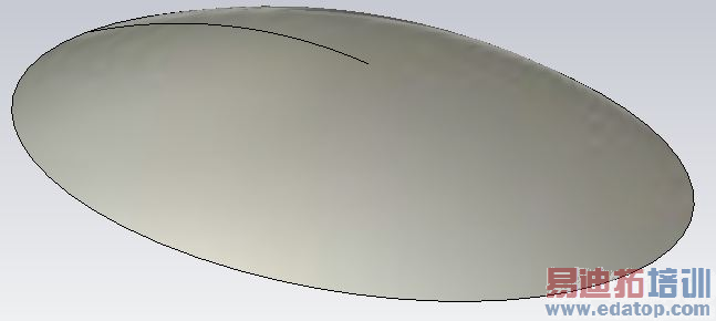
Example: Create face distortion on a reflector
First select the reflector shape then open the dialog to define the settings for the distortion creation Macros  Construct
  Create Face Distortions.
|
Create Face Distortions
|
|
Limitations:
This operations is only working on sheets with one face.
It cannot be guaranteed that the peak-to-peak interval will be accurately met. Small, supposedly insignificant deviations must be expected. If the defined interval could not be met, the deviation value will be shown in the output window.
Non-uniformly spaced grid lines affect the parameterization of the distorted surface in an unwanted way. Therefore, the flatter the face geometry the better the parameterization of the distorted surface and the more curved the face geometry the more affected the parameterization of the distorted surface.
CST微波工作室培训课程套装,专家讲解,视频教学,帮助您快速学习掌握CST设计应用
上一篇:CST2013: Faceted Representation of Shape
下一篇:CST2013: Make Tangent Curve
 最全面、最专业的CST微波工作室视频培训课程,可以帮助您从零开始,全面系统学习CST的设计应用【More..】
频道总排行
- CST2013: Mesh Problem Handling
- CST2013: Field Source Overview
- CST2013: Discrete Port Overview
- CST2013: Sources and Boundary C
- CST2013: Multipin Port Overview
- CST2013: Farfield Overview
- CST2013: Waveguide Port
- CST2013: Frequency Domain Solver
- CST2013: Import ODB++ Files
- CST2013: Settings for Floquet B


