- 易迪拓培训,专注于微波、射频、天线设计工程师的培养
CST2013: Sweep Curve Along Path
 Modeling: Curves
 Curve Tools
 Sweep Curve
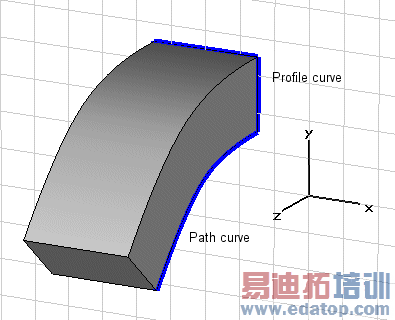
In this dialog box you can sweep a previously defined closed (profile) curve along another existing (path) curve to create a solid shape.
After selecting the corresponding ribbon control an interactive mode will be entered in which the profile curve needs to be selected first before the path curve is selected afterwards.
As soon as the new shape is created it will appear in the main plot window and on the navigation tree.
The picture below shows the shape created by sweeping a rectangle along a spline (additional examples can be found at the end of this page):
Path
This field shows the name of the currently selected path curve. This field is for information purposes only and its contents can not be edited.
Twist angle
Specify the angle to twist the created shape around the path curve.
Taper angle
Specify the angle to taper the created shape along the path curve. A negative angle will taper the shape, a positive angle will flare the shape.
Project profile to path
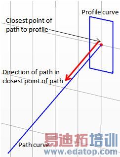
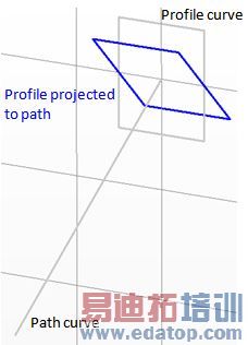
If activated the profile curve is projected onto the path curve by aligning the profile curve with the face normal defined by the path curve.
Component
Choose a new component from the select list. You can also create a new component by typing the name of the new component.
Material
Select the material to which this shape will be assigned from the list of previously defined materials or create a new material by selecting [New Material...]. You can also load a material from the material library by selecting [Load from Material Library...].
OK
Press this button to finally create the shape.
Preview
Press this button to create a preview image of the shape. This option is very useful to check the settings before you actually create the shape.
Cancel
Closes this dialog box without performing any further action.
Help
Shows this help text.
Examples
|
|
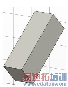
Twist angle: 30°
| Taper angle: 5° |
|
|
Taper angle: -5°
| Twist angle: 30°, Taper angle: -5° |
|
|
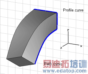
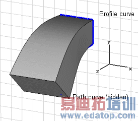
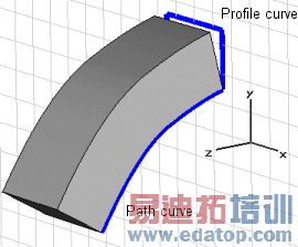
Project profile to path curve turned on
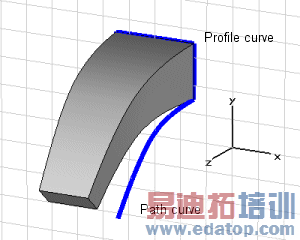
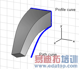
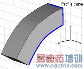
| Project profile to path curve turned off |
Examples: Project profile to path curve
When this option is turned on, the profile is rotated such that the direction of the path in the closest point to the profile is orthogonal to the profile plane.
 |
 |
|
CST微波工作室培训课程套装,专家讲解,视频教学,帮助您快速学习掌握CST设计应用
上一篇:CST2013: Extrude Profile Dialog
下一篇:CST2013: Faceted Representation of Shape
 最全面、最专业的CST微波工作室视频培训课程,可以帮助您从零开始,全面系统学习CST的设计应用【More..】
频道总排行
- CST2013: Mesh Problem Handling
- CST2013: Field Source Overview
- CST2013: Discrete Port Overview
- CST2013: Sources and Boundary C
- CST2013: Multipin Port Overview
- CST2013: Farfield Overview
- CST2013: Waveguide Port
- CST2013: Frequency Domain Solver
- CST2013: Import ODB++ Files
- CST2013: Settings for Floquet B

