- 易迪拓培训,专注于微波、射频、天线设计工程师的培养
CST2013: Time Signal Processing / Exchange Excitation
Home: Macros Macros
 ime Signal Processing
 Exchange Excitation
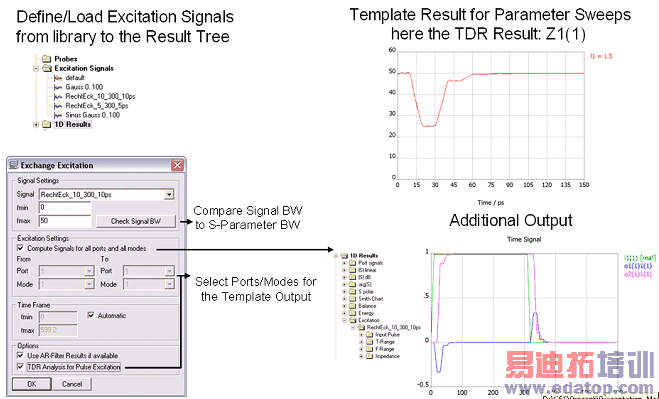
This macro can be used to exchange the excitation signal of a project without rerunning the simulation. Based on the previous simulated S-Parameters (calculated over a sufficiently large frequency band), a new excitation signal can be tested. The macro is able to load and test arbitrary signals preventively defined as Excitation Signals in the tree folder (excitation signal>right click>new excitation signal or load from signal library).
The (nearly) identical solution is available as macro as well as a 1D Result template. The macro is good to exchange the simulation only once, the template should be used, if the operation should be applied also during adaptive meshing, parameter sweeping or optimization.
Signal Setting:
This setting allows loading the arbitrary signals. While changing the frequency range (fmin-fmax) and pressing the Check Signal BW button it is displayed (on-line) how the ideal and the real waveform of the defined excitation signal looks like.
In the case in which the simulation has been run in a frequency range with the upper frequency value lower than the defined one (f-max), needed to get the desired accuracy of the real waveform with the ideal one, please re-run the simulation with the new frequency range. This avoids getting an output signal which is truncated at a time value directly related to the upper value of the simulated frequency range.
Excitation Setting:
It offers the possibility to choose the ports and the mode (e.g. in the case of waveguide ports) which one is interested in.
Switching on the option Compute Signals for all ports and all modes, the complete set of ports/modes will be executed.
Please note that there is also the TDR functionality and the possibility to switch on the AR-filter, in the case in which they have been used in the simulation.

OK
When pressing the ok button a new folder (named T-Range) will appear in the history tree. It contains information regarding the input signal and the output signal, which can be a transmitted signal (on (1)) or a reflected one (in (1)), depending on the selection of the second port. The extra folder F-range contains information (amplitude and phase) regarding the Fourier Transform of the considered signals.
Cancel
Closes this dialog box without performing any further action.
Help
Shows this help text.
CST微波工作室培训课程套装,专家讲解,视频教学,帮助您快速学习掌握CST设计应用
上一篇:CST2013: 3D Scalar Plot
下一篇:CST2013: Display 3D Fields on 2D Plane
 最全面、最专业的CST微波工作室视频培训课程,可以帮助您从零开始,全面系统学习CST的设计应用【More..】
频道总排行
- CST2013: Mesh Problem Handling
- CST2013: Field Source Overview
- CST2013: Discrete Port Overview
- CST2013: Sources and Boundary C
- CST2013: Multipin Port Overview
- CST2013: Farfield Overview
- CST2013: Waveguide Port
- CST2013: Frequency Domain Solver
- CST2013: Import ODB++ Files
- CST2013: Settings for Floquet B
