- 易迪拓培训,专注于微波、射频、天线设计工程师的培养
Problem is real masured & simulation different in CST
录入:edatop.com 点击:
i randomly simulated coil in cst.
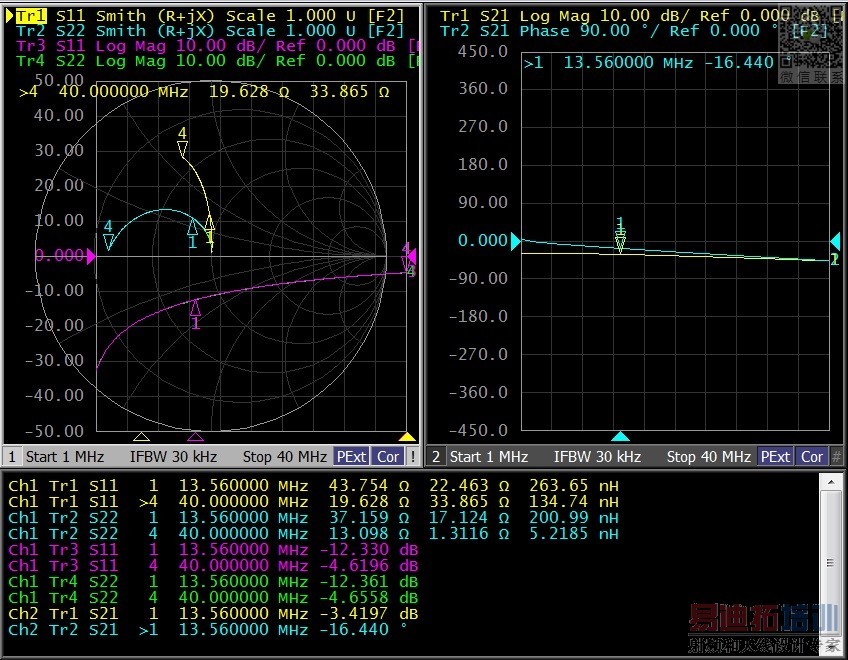
the result is next photo.
1. why impedance is same to all frequency?
2. i really masured coil in Network analyzer
the result is 45~50 ohm
why result is different?
[ATTACH=CONFIG]14184
there is same model
but result is different.
cst & hfss do not trust..... right?
help me solution
the result is next photo.
1. why impedance is same to all frequency?
2. i really masured coil in Network analyzer
the result is 45~50 ohm
why result is different?
[ATTACH=CONFIG]14184
there is same model
but result is different.
cst & hfss do not trust..... right?
help me solution
The problem is your interpretation of results. You compare input impedance into a line (measurement) with characteristic line impedance (simulation). But these are different things.
Thank you for responding to my article.
i understood input impedance & characteristic impedance.
N.A result is input impedance and simulation result is Zo(characteristic impedance).
1.then, what is the reference impedance in cst. only Zo?
2.how can i get input impedance in cst?
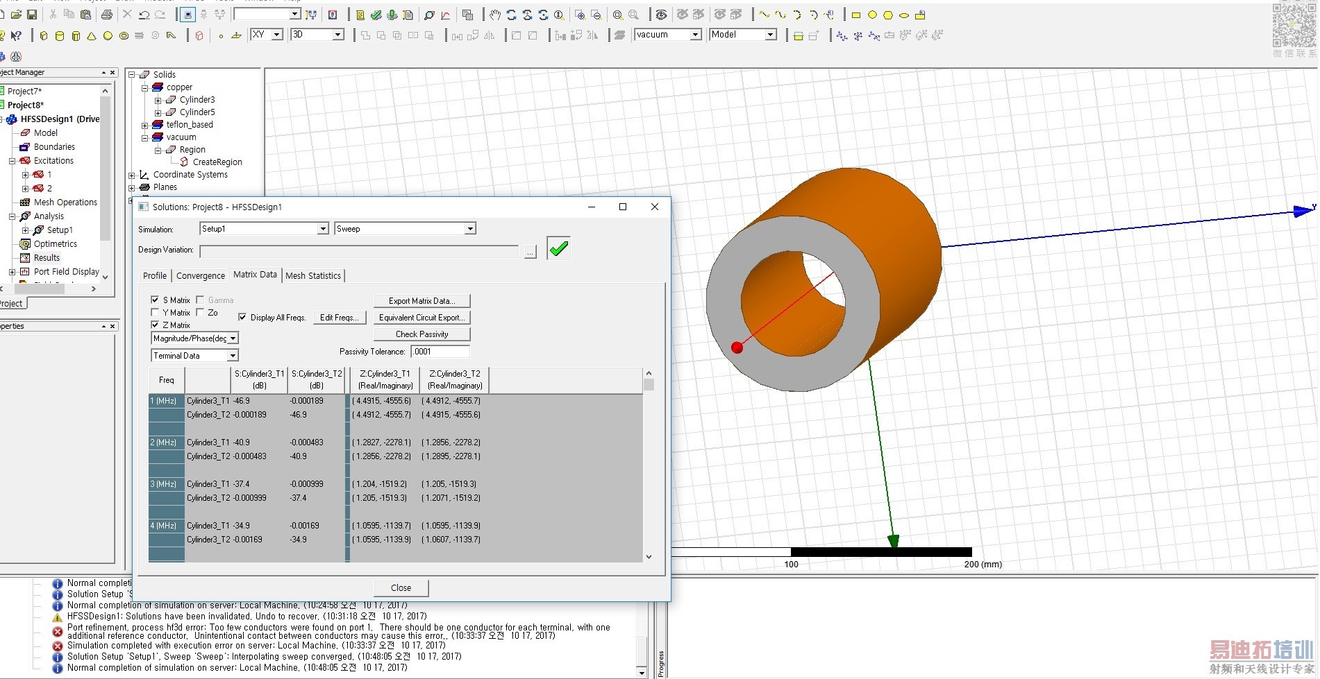
last. why cst & hfss result is different? ex. S, Z matrix value
S-parameter values depend on the chosen reference impedance. You need to be careful what impedance they refer to: 50 Ohm fixed or the line impedance seen at the port ("generalized s-parameters")
I am not a CST user, so I don't know where you can find input impedance in the results. In other tools, it is often called "Zin" or something like that. Verify that the tools gives the value with 50 Ohm termination on the other end, so that you can directly compare to measured. Or calculate it yourself from S11 using the 50 Ohm S-params.
One common reason for difference between EM solver results is the user himself, and his solver settings.
What I do see in your screenshot is a solver warning that simulation stopped before steady state was reached. Check your settings for time steps.
申明:网友回复良莠不齐,仅供参考。如需专业解答,请学习易迪拓培训专家讲授的CST视频培训教程。
上一篇:CST Studio LF transformer example needed
下一篇:请问HFSS11和CST2010仿真的天线模型可不可以转换成CAD模型?
