- 易迪拓培训,专注于微波、射频、天线设计工程师的培养
Using a diode connected transistor model in CST 3D simulation
I simply want to have this in a full 3D simulation.
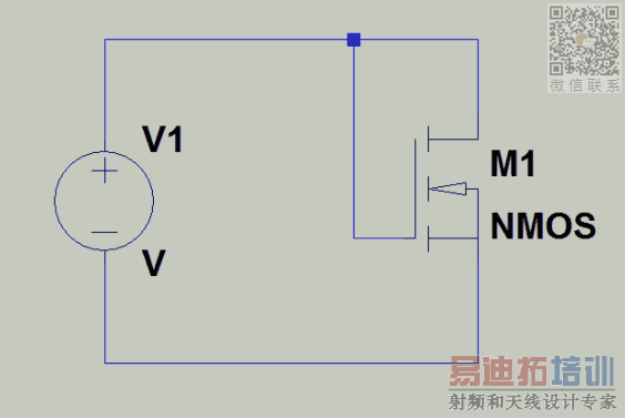
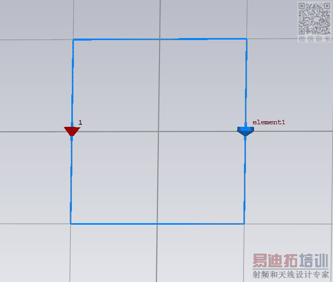
It would look like this (maybe), except, instead of a diode, there would be a transistor model.
I would like to be able to change the transistor model, but I can just start with a random model such as
.model AO6407 VDMOS(pchan Rg=3 Rd=14m Rs=10m Vto=-.8 Kp=32 Cgdmax=.5n Cgdmin=.07n Cgs=.9n Cjo=.26n Is=26p Rb=17m ksubthres=.1 mfg=Alpha_&_Omega Vds=-20 Ron=34m Qg=13n)
How would I go about putting this transistor in diode connected configuration in the simulation?
transistor_model.zip
CST Microwave Studio does not simulate active elements..
Passive components only such as filters,cavities,lumped passive components,antennas etc.
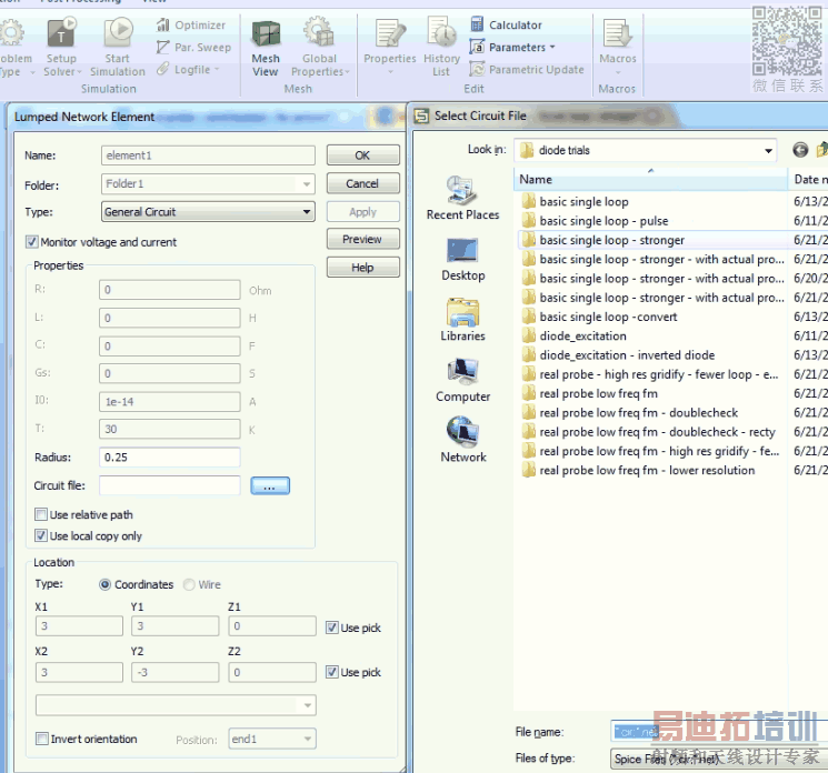
Just to be clear, Microwave Studio can indeed simulate diodes just fine and it allows you to use a .cir/.net file as a lumped element
I realize diodes are technically passive, but i only intend to put in a diode connected transistor, with no additional biasing or anything. It seems like it should be possible.
But the model which you have written above is a nonlinear MOS model.CST cannot understand those statements..
All you can do is to linearize that diode as you have remarked so diode will have simple small signal AC model..Possible ? Try..
But If I were you, I transfer that layout/system/circuit (?) onto Keysight ADS Design Environment if you're able to launch, then I would do my simulations with true nonlinear model..
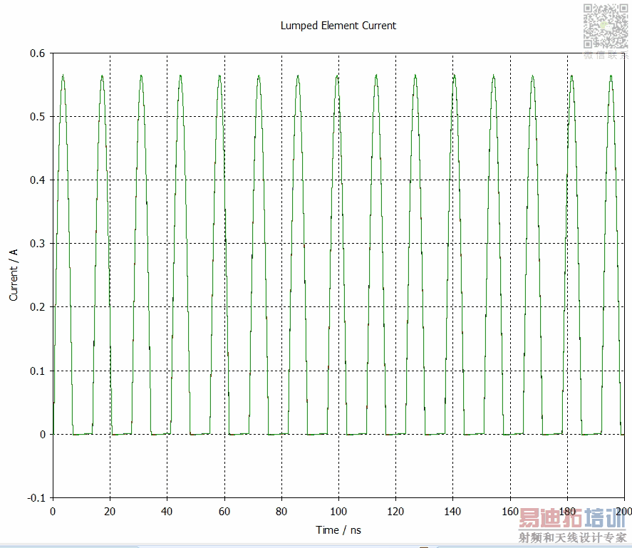
Nonlinear diode works fine with Transient simulation.
You should check if the excitation level can be changed without repeating the EM analysis of the linear passive model parts. It would be inefficient to repeat the EM calculation if only the diode response changes. That's why we usually split into active part (nonlinear, lumped) and EM part (linear, distributed), for workflow efficiency reasons.
申明:网友回复良莠不齐,仅供参考。如需专业解答,请学习易迪拓培训专家讲授的CST视频培训教程。
上一篇:CST Studio: induced signal antenna
下一篇:Cst cable studio h-field coaxial cable


