- 易迪拓培训,专注于微波、射频、天线设计工程师的培养
how to maesure secondary inductor value of Transformer in cst
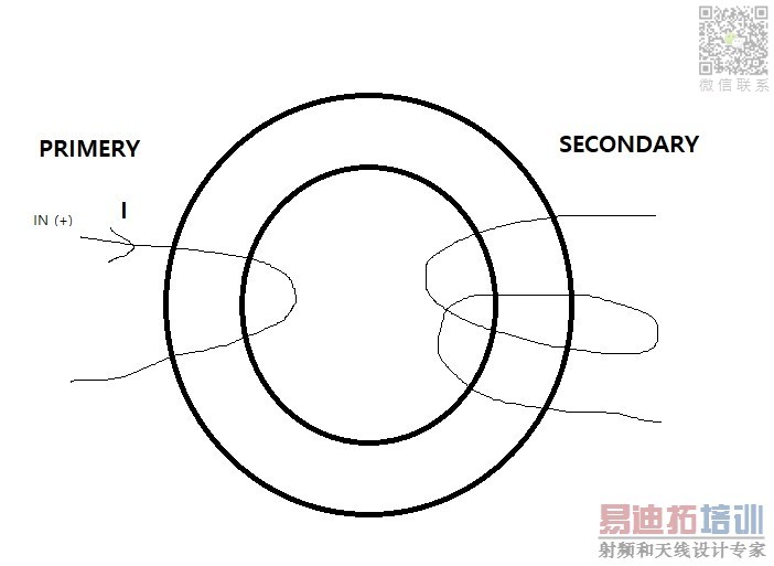
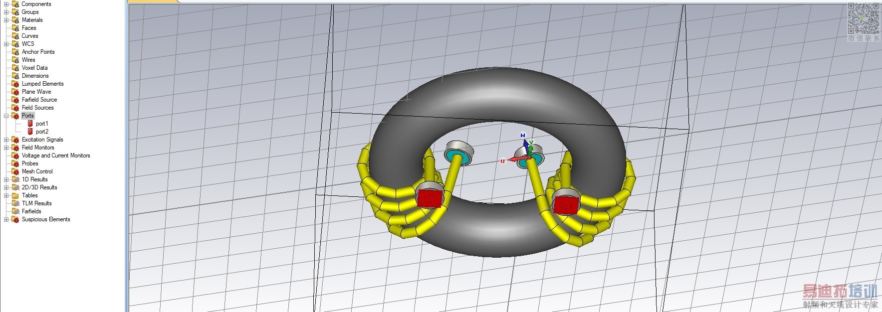
i thought edge of Primary & secondary inductor make port.
each of Primary edge is port 1, port 2
each of secondary edge is port 3, port 4
there is 4 port then
L=l imaginary 1,1 l / 2*pi*f i thought can calculate L value.
this is right?

Measure pri L, then mult x turns^2 for sec L, assuming 1 turn pri.
i want measure secondary L.
In most cases, a transformer will be described as two port rather than 4 port. Analyzing the winding terminals as two port makes sense for RF transformers with differential connection, e.g. a balun. But it's not useful for determining simple parameters like inductance.
As for your calculation, which kind of port parameters do you refer to with "1,1"? Z, S, whatsoever? Also which inductance value are you measuring? Lh, Ls?
I assume you do not have an inductance meter?
I don't think there is a way to measure inductance in CST. You can simulate frequency of the coils and calculate the inductance of the coil using the formula you have given.
the coils shouldn't be 4 ports but only 2 ports. you can connect one edge port between two terminals in the primary coil and one edge port between the two terminals of the secondary coil.
please update me about the results.
The easiest way is to connect an inductance meter to the sec - this will give you the L of the sec in seconds...
In the title of this thread, CST is mentioned which is a simulation tool.
I agree that reducing the model to a 2-port is the easiest way to evaluate inductance, with Y/Z parameters. For secondary inductance with primary coil open, evaluate Z22.
apologies, CST also means, Current Sense Transformer...

i appreciate opinion of your.
i make 2 port.
first, primary port is 1 port and open port ,also secondary port is 1 port and open port.
secondary inductor is calculate result of Z22
L= image Z2,2 / 2 * pi * f right?
No, your ports are wrong. How can current flow there, with 4 ports where all port grounds are floating?
Use lumped port between the ends of each coil.
pls follow the instruction i have given. you have 4 ports which is wrong. the port is waveguide port whereas u need edge port as i mentioned earlier.
um... i serch to various opinion.
how to make edge port in CST?
there are Wave,discret,plane,lumped port.
Not sure what pragash means, but let me repeat: Use lumped port between the ends of each coil, so that current can actually flow through the coils.
its Discrete edge port or discrete port.
申明:网友回复良莠不齐,仅供参考。如需专业解答,请学习易迪拓培训专家讲授的CST视频培训教程。
上一篇:T-SRR Antenna design using CST . Help needed
下一篇:求助CC2541 i2c问题,I2CSTAT一直等于0xf8,且一直while ((I2CCFG & I2C_SI) == 0);跳不出来

