- 易迪拓培训,专注于微波、射频、天线设计工程师的培养
CST strange radiatin pattern problem
录入:edatop.com 点击:
Dear all,
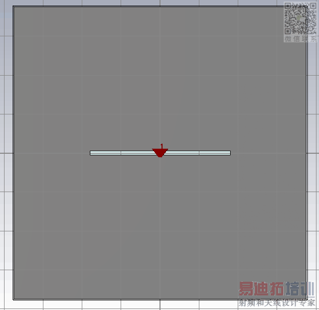
I am designing a simple slot antenna (just a rectangular cut in the ground plane) at 75GHz on a thick Si substrate . The slot has a length of 740um and a width of 22um as shown in next figure
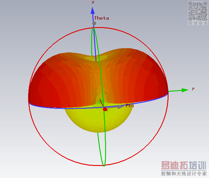
for a small ground plane (1500 x 1500 um), the radiation pattern is perfect. It resembles that of a dipole but radiates strongly in the substrate side, as shown
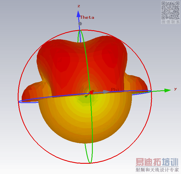
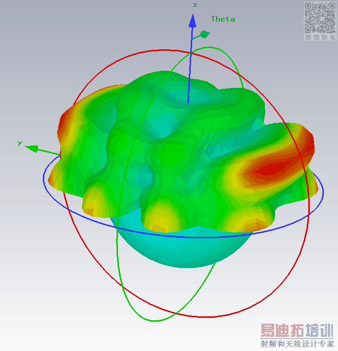
However, when I increase the size of the ground plane and the substrate to 3000 x 3000 um, the radiation pattern becomes worse, as shown
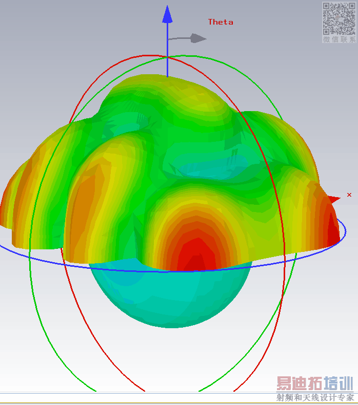
The pattern keeps becoming worse when I increase the dimension of the ground plane and the substrate. Shown is the pattern for 5000 x 5000 um substrate
For 7000 x 7000 um, it is even worse:
And when I increase the thickness of the substrate to 4000 um to make it as if it is infinite, I get the following beam shape
S and Z parameters are the same for all cases.
I don't think it is a meshing problem because I mesh the critical regions very well. I also used Adaptive meshing and increased the simulation upper frequency but no use.
Having a large ground plane is important because finally I will design an array out of this slot.
Regards
Check if accuracy level is set -40db, sometimes is better to use -60db for antenna (Time domain solver). Is it broadband farfield or specific frequency?
申明:网友回复良莠不齐,仅供参考。如需专业解答,请学习易迪拓培训专家讲授的CST视频培训教程。
上一篇:How do you export 3D model views in CST MWS 2014?
下一篇:Calculaton RCS in CST

