- 易迪拓培训,专注于微波、射频、天线设计工程师的培养
Open circuit and short circuit a port on CST
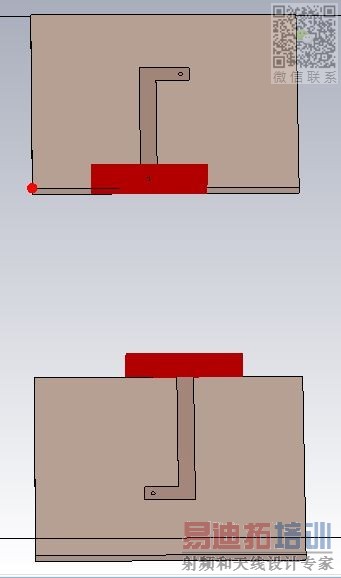
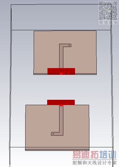
I have designed 2 printed antennas (tell them (1),(2)) in CST.
Now, i want to measure the S1,1 and S1,2 with the (2) antenna open-circuited and short-circuited.
What is the procedure in order to do that?
Thank you very much. My question might be stupid, but i'm a beginner. I would really appreciate any kind of help.
I understand that you have one model with two antennas, and each antenna is connected to a port.
Now you want to simulates the interaction between the two antennas.
First you get S21 from the 2-port simulation.
Then, instead of creating two additional 1-port EM models (one with antenna 2 shorted, the other with antenna 2 open) you can use the existing 2-port simulation and calculate input impedance from Y11 and Z11. Y11 is the input impedance into port 1 with all other ports shorted, Z11 is the input impedance into port 1 with all other ports open. So this gives you all the results from one 2-port simulation.
Thank you very much for your help! I got it.
One more question:
Should I orient the pcbs or the ports in order to have satisfactory results?
Take a look at the pictures to understand what i'm saying.
申明:网友回复良莠不齐,仅供参考。如需专业解答,请学习易迪拓培训专家讲授的CST视频培训教程。
上一篇:Thickness of substrate of microstrip antenna in cst
下一篇:metamaterial micostrip antenna using cst microwave studio


