- 易迪拓培训,专注于微波、射频、天线设计工程师的培养
EBG structure modeling in CST with problem of Zmax and Zmin
录入:edatop.com 点击:
Hello friends,
I am working with EBG designs and need to find reflection phase diagram for the same in [1]. I am using CST Studio Suite 2010 (MWS) for my simulations.
The boundary condition is as following image:Xmin Xmax Ymin Ymax unit cell / Zmax Zmin open(add space) .Both are in frequency domain solver.
The number of floquet modes is 2 (TM(0,0) and TE(0,0)).
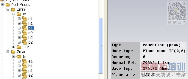
When i calculate the reflection phase by the 'template based postprocessing : arg(SZmaxTM(0,0)ZmaxTM(0,0)) and arg(SZmaxTE(0,0)ZmaxTE(0,0)) .
I find the distance to reference plane of Zmax and Zmin has impact on the results, it the curves of TM and TE are not the same
So what is the appropriate value of the distance of reference plane?
Now we choose the value at "plane at Z"
[1]Comparative Study on Graphene-based Articial Magnetic Conductor (AMC)
I am working with EBG designs and need to find reflection phase diagram for the same in [1]. I am using CST Studio Suite 2010 (MWS) for my simulations.
The boundary condition is as following image:Xmin Xmax Ymin Ymax unit cell / Zmax Zmin open(add space) .Both are in frequency domain solver.
The number of floquet modes is 2 (TM(0,0) and TE(0,0)).
When i calculate the reflection phase by the 'template based postprocessing : arg(SZmaxTM(0,0)ZmaxTM(0,0)) and arg(SZmaxTE(0,0)ZmaxTE(0,0)) .
I find the distance to reference plane of Zmax and Zmin has impact on the results, it the curves of TM and TE are not the same
So what is the appropriate value of the distance of reference plane?
Now we choose the value at "plane at Z"
[1]Comparative Study on Graphene-based Articial Magnetic Conductor (AMC)
Vary the distance using sweep. Beyond a distance the curve will not vary and you can decide from it. Experts suggest to have min distance of lamda/4.
申明:网友回复良莠不齐,仅供参考。如需专业解答,请学习易迪拓培训专家讲授的CST视频培训教程。
上一篇:help simulat EBG structure using CST
下一篇:Simulating Losses in Coaxial Cables at CST MWS
