- 易迪拓培训,专注于微波、射频、天线设计工程师的培养
How can i simulate a perfect waveguide with no reflections (S11) in CST ?
录入:edatop.com 点击:
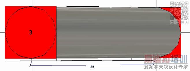
Currently i'm making a circular waveguide feeding by two monopole and i would like to determine the perfect S21 in the waveguide without the waveguide reflections.
I try to use some materials from the library (Eccosorb) to cut off the reflections at the start and at the end of the waveguide, without concrete results.
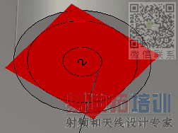
In attach you will find my CST drawing,
Thank you in advance for your answer.
2 :
3:
4:
I try to use some materials from the library (Eccosorb) to cut off the reflections at the start and at the end of the waveguide, without concrete results.
In attach you will find my CST drawing,
Thank you in advance for your answer.
its really new for me but i can try to answer.
s11=b1/a1 when a2= 0. a2= reflected wave from port 2. so you have terminate the other port with perfect 50ohm/correct impedance in order to get ideal reflection is S11=0.
Hi Pragash,
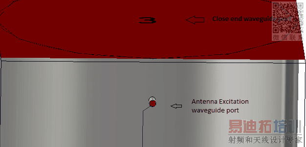
Yes i've tried to set up waveguide port at the end of the duct (both end), then i choosed in the the setup solver the right excitation port (antenna only). I hope when i don't feed waveguide port they will behave as matched loads.
If you have others advice, don't hesitate to post !
can you share the picture of waveguide port close up, S21 and etc so it will be easy to help you
Hi Pragash,
You will find in attach my CST drawing and CST parameters.
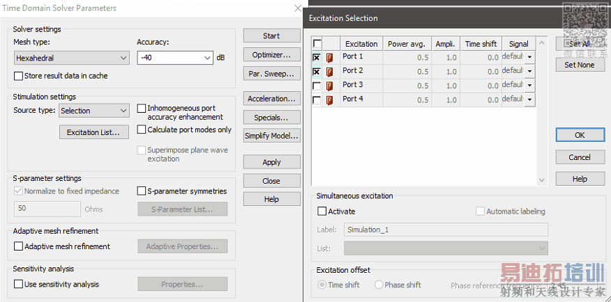
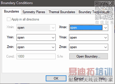
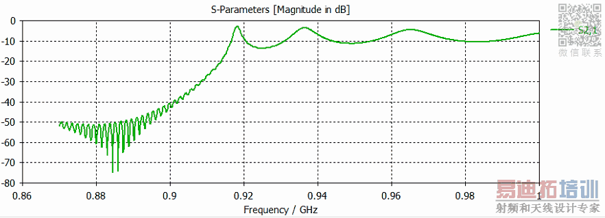
I've set up the waveguide port 3 and 4 at the end of the circular waveguide without excitation and i've set up an excitation for the port 1 and 2 to feed the antennas. You will also find in attach the boundaries parameters and the result of the S21 that i've experienced.
Thank's for your time Pragash,
does your waveguide port touches ground and signal at port 1 and port 2?
just enable adaptive mesh refinement and you will get sensible results without resonance at 0.88GHz.
Hi Pragash,
You will fin in attach the result with the adaptive mesh refinement.
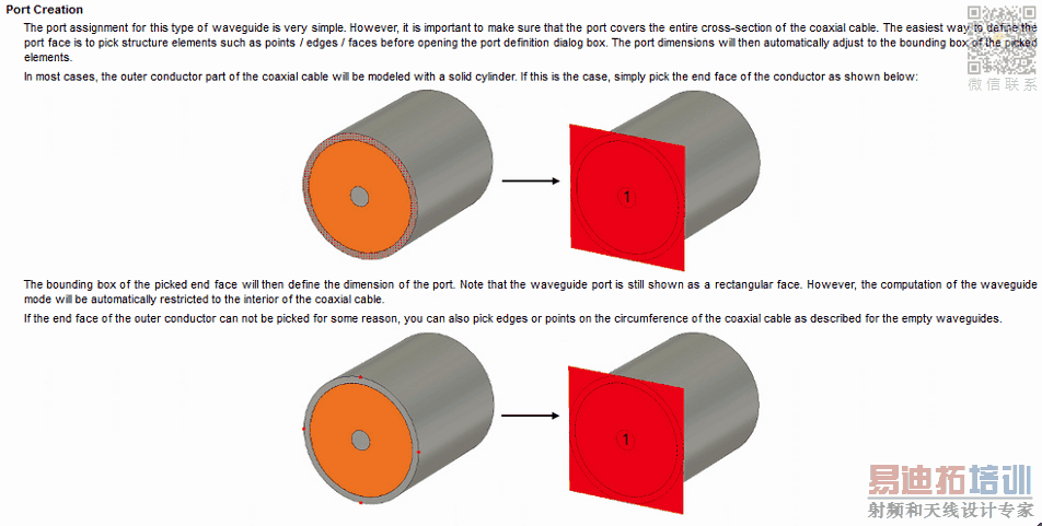
About the waveguide port 1 and 2, i set up these waveguide port by choosing the dielectric surface. I suppose like that, the waveguide port is large enough for the impedance calculation by covering the dielectric and the antenna feeding. But i found in CST HELP it was advised to cover the entire cross-sections.
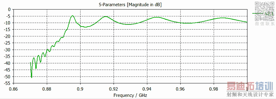
I decided to reload two simulations :
- Picture 3 it's mesh refinement + waveguide port covering dielectric and antenna feeding only.
- Picture 4 it's mesh refinement + waveguide port advice covering the entire cross-sections of the coaxial cable.
Thank's for your time Pragash,
1 :
2 :
3:

4:
looks like picture two has signal in the middle and ground at the edge. so your port creation also correct.
i have never done such design (monopole feeding circular waveguide) so i dont know how to advice you from your design perspective. i did advice you from general simulation guide to see if you are doing anything wrong in your simulation setup. if you share more about your design, i will try to help you..
Hi Pragash,
Thank's for you time.
I'm going to use a network analyser in order to compare CST result with the experimentation.
If you're interested about the results, i can keep you updated !
Thank's
hi pierre_B,
sure. please keep me updated. i would like to learn together with you.
申明:网友回复良莠不齐,仅供参考。如需专业解答,请学习易迪拓培训专家讲授的CST视频培训教程。
上一篇:simulating a line source on CST Microwave Studio
下一篇:how to cut a triangle from a square in cst MWS
