- 易迪拓培训,专注于微波、射频、天线设计工程师的培养
[CST ] Waveguide Port Unstability error.
录入:edatop.com 点击:
Dear Members
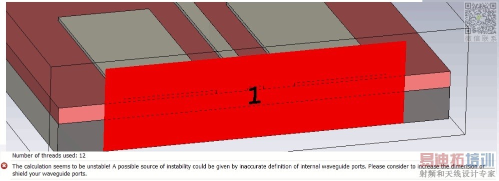
I am working on a design having a Grounded Co-Planar Waveguide feeding structure. The substrate is Silicon Dioxide (SiO2) and the freq is 200 THz.
When exciting with a waveguide port I am getting the following error;
I tried to add shielding effect and increase the size of waveguide port as well, but all in vain.
Kindly someone please help me resolve this error.
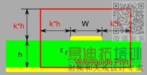
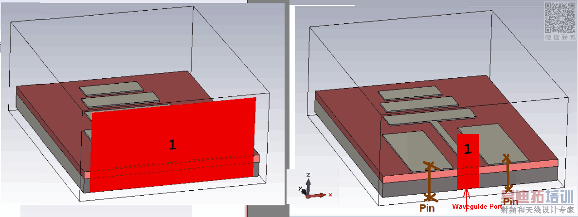
A possible source of errors are the port dimension. Your vertical port extension looks quite small. It should be approx. 4-5 times the substrate height. But maybe have a closer look into the manual.
,,,,
@fiwi and @johnjoe: I tried both of the solutions presented here. But still no solution.
,,,,
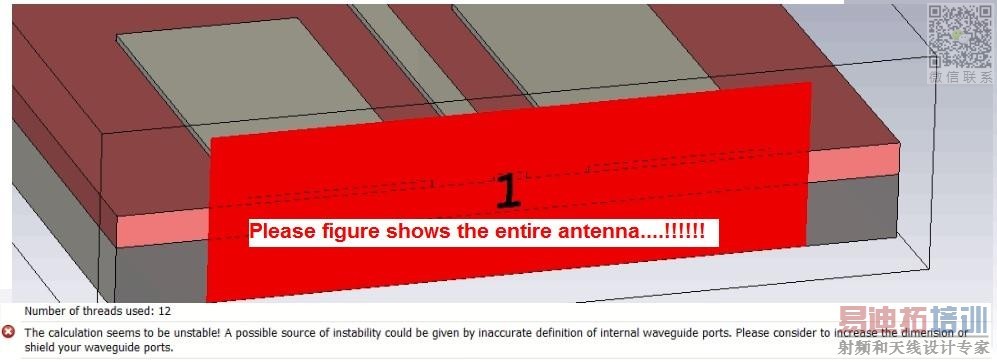
@fiwi: Its a Yagi uda antenna.
@K3k, I think it should look like...
@fiwi: Let me give it a try.
@fiwi: Let me give it a try.But what is Pin? Are they separate feeds or something else>
And I may Have to excite the two grounds on top as well..Left and Right, Pin marked by you as it is CPW.
@k3k,better said hole-pins, are like a shortcircuit with the ground.
@fiwi: I did short circuit and reduces the port dimensions as per your suggestion but still same problem. :(
Give me dimensions or simulation cst if you can ...!
@fiwi.Ok.I will PM you the file.
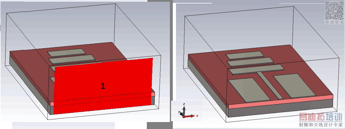
How did you set your boundary conditions? If you want to excite a cpw mode as your setup suggested, the port setup of the 7th post is wrong. I don't know your setup dimensions but maybe it helps to extend your feeding line in the -y direction and increase the areas of the ground planes next to both sides of your feeding line.
@johnjoe: Thnx for the suggestion. I am using OPEN (ADD SPACE) asboundry conditions for ths structure.
I can try to extend the feedline and the ground next to it and then try excitation. Will update u accordingly.
P.S. What do you mean by: " the port setup of the 7th post is wrong"
I mean the right pic of the 7th port, it's not correct if you want to excite cpw mode.
@johnhoe: can suggest the correct one please, using the image above.
Just have a look in the help function of CST: Help -> Microwave Studio -> Excitation Sources -> Waveguide Port Overview -> Coplanar Lines. Your case is well explained there and also the right dimensions and extensions.
@johnJoe: Thnx for the guidance, but I did go through the port assigning techniques in the manual. But it gives the same error.
If I shield the waveguide port, it gives the error of "Reducing the stability factor". Which when done still doesn't solve the problem.
,,,,!?
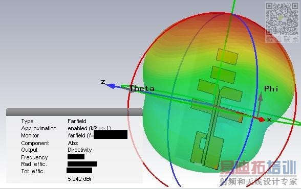
@fiwi: What you want to express with this pic. Does his simulation work or doesn't? Is the sim correct? Is the em-mode correct? You just show some radition pattern without any useful information. Everything will radiate somehow.
@kela3kela: Did you tried to extend?
申明:网友回复良莠不齐,仅供参考。如需专业解答,请学习易迪拓培训专家讲授的CST视频培训教程。
上一篇:How to find nput impedance of FSS unit cell in CST MWS
下一篇:how to simulate PMC in CST
