- 易迪拓培训,专注于微波、射频、天线设计工程师的培养
CST Boundary conditions
录入:edatop.com 点击:
Hi everyone,
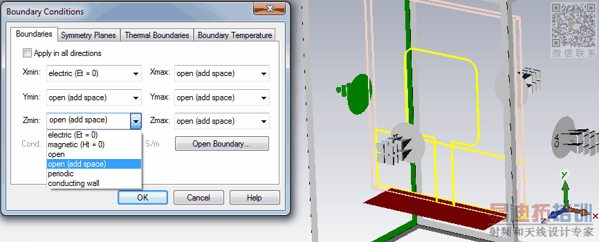
Anyway, I'm just a beginner in CST and your help will be appreciated. I just designed an UWB antenna in CST MWS, the antenna is : microstrip rectangular patch, partially grounded substrate. BACKGROUND MATERIALS set to NORMAL, Waveguide PORT was designed accordingly. Now, here's my problem: BOUNDARY CONDITIONS. When I set them ALL to open (add space), the simulation just looks like in the paper or much similar. When changing them , the result will be different and undesired. Could you share some hints regarding to boundary conditions. Please see the attached image.
Thank you.
申明:网友回复良莠不齐,仅供参考。如需专业解答,请学习易迪拓培训专家讲授的CST视频培训教程。
上一篇:How disign two coax antenna with same refrence- cst
下一篇:CST simulation with unit cell boundary condition


