- 易迪拓培训,专注于微波、射频、天线设计工程师的培养
Interdigital Capacitor - CST2013 MWS Examples
General Purpose Hexahedral: |

General Description
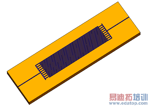
The Interdigital Capacitor example shows the extraction of a SPICE compatible network model based on the scattering parameter calculation. The structure has nine long fingers on each side located on an aluminium oxide substrate. The feeding is realized with waveguide ports and a metallic connection.
Structure Generation
The structure's modelling starts with the definition of the substrate consisting of a dispersive Debye material. The frequency selective material behavior can be studied in the 1D Results  Materials folder.
The ground plate has not to be modelled with an extra shape because an electric boundary condition on the bottom of the substrate can be used. Thereafter the feeding from one side is modelled. Afterwards one finger is defined from the branching and transformed eight times. Another two transformations mirror the structure to the whole model.
The waveguide ports are extended to the full range in order to get the desired Quasi-TEM Modes.
Mesh Settings
The mesh type was set to "Hexahedral Mesh" in the frequency domain solver dialog.
Solver Setup
For this example only the network parameters at the frequency of 500 MHz are of interest. Therefore a single frequency point was defined. The frequency domain solver then will only calculate the S-Parameters of the structure for a frequency of 500 MHz.
In order to get the electric and magnetic fields at the calculation frequency the Save all field results check box was activated.
Since a single frequency sample will be calculated, the broadband frequency sweep is disabled.
The remaining setting need not to be changed.
Post Processing
The results you directly receive are the electric and magnetic fields and the scattering parameters at the calculation frequency.
With the resulting S-Parameters a SPICE compatible network model considering one cascade for a frequency of 500 MHz was extracted. Open the Post Processing: Signal Post Processing  Network Parameters
 Transmission Line... dialog and press the Show Results button to see the calculated network parameters. They show a high capacitance at 500 MHz and only a small inductance. Furthermore the lossy behavior of the Debye material is reflected in the not negligible resistance value of the structure.
For further processing using SPICE you can export the netlist.
CST微波工作室培训课程套装,专家讲解,视频教学,帮助您快速学习掌握CST设计应用
上一篇: Farfield Source - CST2013 MWS Examples
下一篇: Folded Patch Antenna - CST2013 MWS Examples
 最全面、最专业的CST微波工作室视频培训课程,可以帮助您从零开始,全面系统学习CST的设计应用【More..】
频道总排行
- Rectangular Waveguide Tutorial
- FSS: Simulation of Resonator
- CST2013 MWS Examples: Thermal C
- Dipole Antenna Array - CST201
- CST MWS Examples - CST2013 M
- Microstrip Radial Stub - CST2
- Dielectric Resonator Antenna -
- Interdigital Capacitor - CST20
- CST2013 MWS Examples: Biological
- Lossy Loaded Waveguide - CST2
