- 易迪拓培训,专注于微波、射频、天线设计工程师的培养
Defected Ground Structure - CST2013 MWS Examples

General Description
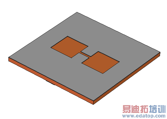
In this example the scattering parameters of a simple microstrip line with an interrupted ground plane are calculated. (The image above displays this defected ground plane.)
Structure Generation
The general settings for this example are optimized for a planar microstrip coupler. The boundaries are set to magnetic type to prevent the excitation of auxiliary box modes.
Please note, that the Project Template Wizard guides you to easily setup specialized and predefined templates for certain application areas.
The entire structure is created by defining basic bricks and using the extrusion tool and the mirror operation. The holes in the ground plane are formed by subtracting several bricks from it.
The background (which is the calculation domain) is enlarged in both positive and negative z-directions in order to minimize the effect of the boundary conditions on the solutions.
Solver Setup
The microstrip line is terminated at both sides by waveguide ports which propagate the fields into and out of the structure. For this example only the fundamental mode needs to be considered. The excitation signal is a Gaussian shaped pulse referring to the frequency range from 0 to 10 GHz.
The symmetry of the structure is taken into account by using a magnetic symmetry condition. Since the structure is loss-free and has only two ports, the entire S-matrix can be obtained by just a single simulation run. The check for a loss-free two-port structure is activated by switching on Simulation: Solver  Start Simulation
  Time Domain Solver
 Specials...
  General
  Consider two port reciprocity.
Post Processing
The S-Parameters are available in the folder 1D Results in the navigation tree. This folder contains also the evolution of the total field energy over the time and the energy balance of the S-Parameters.
The port modes and the result of the previously defined electric field monitor can be found in the 2D/3D Results folder.
CST微波工作室培训课程套装,专家讲解,视频教学,帮助您快速学习掌握CST设计应用
上一篇: Dipole on thin substrate using local multilayer - CST2013 MWS Examples
下一篇: Circulator - CST2013 MWS Examples
 最全面、最专业的CST微波工作室视频培训课程,可以帮助您从零开始,全面系统学习CST的设计应用【More..】
频道总排行
- Rectangular Waveguide Tutorial
- FSS: Simulation of Resonator
- CST2013 MWS Examples: Thermal C
- Dipole Antenna Array - CST201
- CST MWS Examples - CST2013 M
- Microstrip Radial Stub - CST2
- Dielectric Resonator Antenna -
- Interdigital Capacitor - CST20
- CST2013 MWS Examples: Biological
- Lossy Loaded Waveguide - CST2
