- 易迪拓培训,专注于微波、射频、天线设计工程师的培养
Microstrip Capacitor - CST2013 MWS Examples
General Purpose Hexahedral: | |
General Purpose Tetrahedral: |

General Description
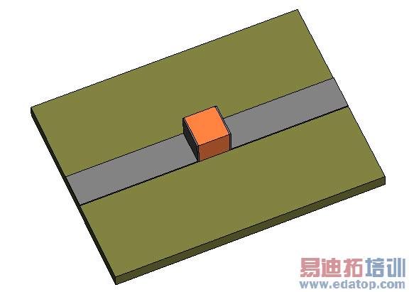
This example shows a microstrip line with a plate capacitor inside. It demonstrates the usage of waveguide ports for microstrip devices and symmetry planes for symmetric devices.
The results are focused on the extraction of a SPICE compatible network model for a frequency of 0.5 GHz.
The same structure has been simulated with the general purpose hexahedral and tetrahedral frequency domain solvers.
Structure Generation
The modelling of the structure starts with the definition of the units and the background material, in this example air (normal). In this dialog the distance between the microstrip line and the bounding box is also defined. Then the definition of the substrate layer follows. The ground plate has not to be modelled with an extra shape because an electric boundary condition on the bottom of the substrate can be used. Afterwards the two stripline feedings were modelled. The plate capacitor was created using two metallic plates and a relative high dielectric (epsilon relative = 12).
Last but not least comes the definition of the waveguide ports. They are extended to full range in order to get the desired Quasi-TEM Modes.
For this symmetric structure a magnetic symmetry plane was introduced that speeds up the solver.
Some elements have been defined parametrically with the following parameters:
gap | 0.5 | length of the capacitance |
t_length | 4 | total length |
t_width | 3 | total width |
width | 0.5 | stripline width |
Mesh Settings (General Purpose Hexahedral Solver)
The mesh type was set to "Hexahedral Mesh" in the frequency domain solver dialog.
Solver Setup
The SPICE parameter network extraction can either be done as a postprocessing step after the calculation or the field calculation can be done automatically from the SPICE parameter network extraction. This example shows the second way: The frequency domain solver was started by pressing the Calculate button in the SPICE parameter network extraction dialog.
The main settings for the solver are made in the frequency domain solver parameters dialog. For this example the Save all field results check box was activated in order to receive the electric and magnetic fields at the calculation frequency.
Since a single frequency sample will be calculated, the broadband frequency sweep is disabled.
Post Processing
As a result you can view the scattering parameters as well as the electric and magnetic fields for the calculation frequency. With the resulting S-Parameters a SPICE compatible network model considering one cascade for a frequency of 500 MHz can be extracted by opening the Post Processing: Signal Post Processing  Network Parameters
 Transmission Line... dialog and pressing the Show Results button to see the calculated network parameters. To export a netlist for further calculations using SPICE, press the Create Netlist button.
CST微波工作室培训课程套装,专家讲解,视频教学,帮助您快速学习掌握CST设计应用
上一篇:CST2013 MWS Examples: Yagi Antenna
下一篇: RCS Calculation of a Large Transport Ship - CST2013 MWS Examples
 最全面、最专业的CST微波工作室视频培训课程,可以帮助您从零开始,全面系统学习CST的设计应用【More..】
频道总排行
- Rectangular Waveguide Tutorial
- FSS: Simulation of Resonator
- CST2013 MWS Examples: Thermal C
- Dipole Antenna Array - CST201
- CST MWS Examples - CST2013 M
- Microstrip Radial Stub - CST2
- Dielectric Resonator Antenna -
- Interdigital Capacitor - CST20
- CST2013 MWS Examples: Biological
- Lossy Loaded Waveguide - CST2
