- 易迪拓培训,专注于微波、射频、天线设计工程师的培养
CST2013 MWS Examples: One-way Transmission Device
录入:edatop.com 点击:
General Description
In this example the characteristic behavior of a one-way transmission device is presented by the calculation of the corresponding S-parameters.
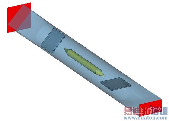
The main structure consists of the rotation domain, containing a centered and magnetized ferrite rod as well as two by 45 degrees rotated damping plates. A propagating wave is rotated inside the circular waveguide by 45 degrees because of the gyrotropic behavior of the biased ferrite material. This means that a wave travelling in one direction is not absorbed in the damping plates, while the wave travelling in reverse direction will be strongly absorbed. This is ensured by the non-reciprocal character of the ferrite, rotating the fields in the same direction, independently of the propagating direction.
The definition of various field and energy monitors offers different visualizations of this wave propagation.
Structure Generation
The one-way transmission device is a waveguide structure and thus the corresponding waveguide template is chosen to define the PEC boundary and background material as well as the units settings.
The solid shapes are constructed by creating bricks and cylinders and the application of the loft functionality.
The anisotropic and dispersive material character of the biased ferrite is defined by the corresponding layer parameters, here referred to the SI-system, however, it is also possible to define the parameters in Gauss units.
Solver Setup
Two waveguide ports are defined at the ends of the given waveguides to perform the S-parameter calculation. The excitation signal is a Gaussian shaped pulse referring to the frequency range from 9 to 12 GHz.
In order to get an additional visualization of the non-reciprocal wave propagation a power flow monitor is defined at an appropriate operation frequency of 10.6 GHz.
Post Processing
The resulting time signals and the corresponding scattering parameters of the transient calculation are listed in the navigation tree in the folder 1D Results. Regarding the absolute value of the S-parameters the non-reciprocal wave propagation can be analyzed. At the frequency 10.6 GHz the energy excited at port No.1 is coupled to port No.2, while in the reverse direction the energy is absorbed in the damping plates.
This result can also be visualized by plotting the monitored power flow, which can be found in the folder 2D/3D Results.
CST微波工作室培训课程套装,专家讲解,视频教学,帮助您快速学习掌握CST设计应用
上一篇:CST2013 MWS Examples: Plate
下一篇:CST2013 MWS Examples: Signal Integrity: Simulation of Via Model
CST培训课程推荐详情>>
 最全面、最专业的CST微波工作室视频培训课程,可以帮助您从零开始,全面系统学习CST的设计应用【More..】
频道总排行
- Rectangular Waveguide Tutorial
- FSS: Simulation of Resonator
- CST2013 MWS Examples: Thermal C
- Dipole Antenna Array - CST201
- CST MWS Examples - CST2013 M
- Microstrip Radial Stub - CST2
- Dielectric Resonator Antenna -
- Interdigital Capacitor - CST20
- CST2013 MWS Examples: Biological
- Lossy Loaded Waveguide - CST2