- 易迪拓培训,专注于微波、射频、天线设计工程师的培养
CST MWS频域1D结果的归一化问题
录入:edatop.com 点击:
仿真结果1Dresults中的时域信号都是有幅度信息的,而频域的结果(如端口电压电流等)好多都是归一化的,也没写清楚单位。
相当于只有频率分布,没有幅度信息,求教怎么得到完整的频谱?
相当于只有频率分布,没有幅度信息,求教怎么得到完整的频谱?
不太懂你的意思
电压电流没有进行归一化,只是对功率进行了归一化
S参数都是比值,这个就没有归一化的说法了
你想得到什么结果呢?
比如我做一个接收天线,看到的接收频谱就是归一化的,上面写着nomalized
没找到你说的归一化频谱。我随便弄了个天线就得到个时域信号。
截个图或者具体说说叫什么。或者干脆上CST文件吧
多谢帮助,图见附件,激励天线端口获得的是S参数曲线,外部激励,天线做接收得到归一化频谱F
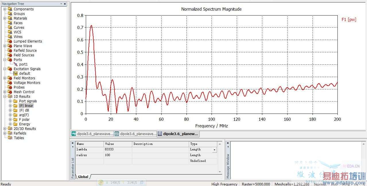
这个应该是平面波激励得到的天线端口上的激励吧?
这个相当于是端口得到的信号/激励的幅度,本来就是个比值
请参考帮助文件中的《Reference Value and Normalizing》一部分:
S-Parameter and F-Parameter calculation
In general, S-Parameter results are given as the ratio of incident and reflected voltage wave spectra at a port, where only one port is excited and all others are perfectly matched. Consequently, for transient simulations, all port signals first have to be transformed into the frequency domain, providing broadband results for one port excitation with only one simulation run.
However, in the case of simultaneous excitation several ports are stimulated at once, so it is not possible to apply the general S-Parameter definition. Now the incident and reflected spectra are given as so-called incident and reflected F-Parameters, all normalized to the spectrum of the reference signal. Furthermore, as an additional result and for a better analysis of the structure's behavior, the reflected spectra of all excited ports are normalized to their own incident spectra, respectively, providing so-called active S-Parameters. Since there might be more energy absorbed at a specific port than it itself has injected, the resulting curves could show active behaviour with values greater than one.
Please note that also in the case of a plane wave or field source excitation, the outgoing signals at ports are used to determine F-Parameters as described above.
谢谢你可是激励信号本来也是个宽频带的时域信号,作为基准的激励信号幅度是指激励信号频谱的最大值?还是各个分别对应各个频点的幅度
另外请教一下CST中是否自带傅里叶变换工具
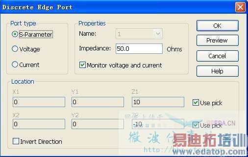
谢谢5l和6l的回答,我是用时域脉冲平面波照射天线,看端口的耦合电压,如下图(第1个图)设置(即加离散端口、不激励、选择监测port的电压和电流)
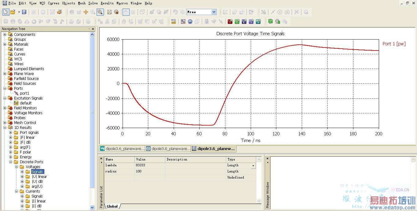
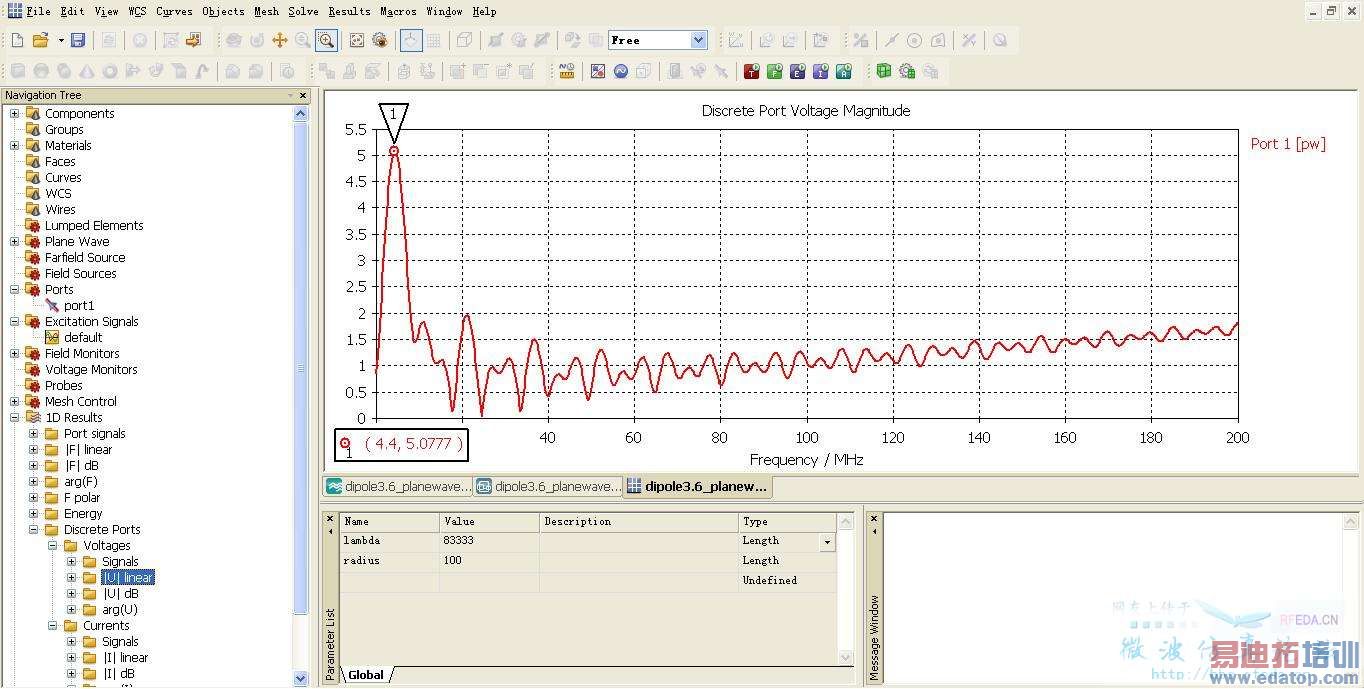
1Dresults中port电压项中:时域电压信号幅度是正常的(第2图),频域的形状对,幅度是不对的。(不知道CST有没有自带傅里叶变换。)
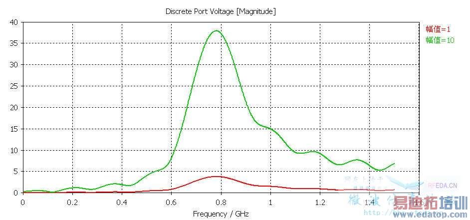
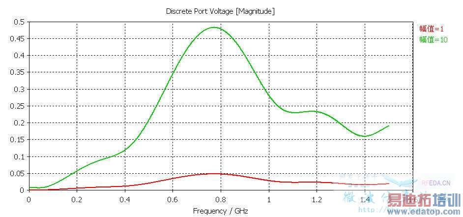
就是比如我把激励信号放大一千倍,按理说这是一个线性系统,那么port的电压频谱幅度应该hi形状不变而幅度变大十倍。可是实际结果是频域幅度和激励放大之前是完全一样的(都是第3个图)
先回答你的问题,是有傅立叶变换的,在后处理里面
首先load 1D data file,然后再选择Fourier Transforms
这个是可以看成一个线性系统,激励幅度增加100倍,输出直接乘以100就好了
这是我随便找了个天线仿了下,得到的结果
申明:网友回复良莠不齐,仅供参考。如需专业解答,请学习易迪拓培训专家讲授的CST视频培训教程。
上一篇:CST MWS中的远场方向图如何归一化
下一篇:CST PCBS出错?
